


Метеостанция на базе Arduino
Неимоверная популярность домашних метеостанций, показывает, что не только фермеры интересуются погодой. Многие люди хотят иметь возможность отслеживать и записывать погодные события в их местности.
Погодные станции обычно состоят из двух основных частей: датчиков, которые расположены снаружи для измерения температуры, скорости (направления) ветра, влажность, осадки, и барометрического давления. И дисплей, который находится внутри в удобном месте. Как правило, внешние датчики соединины вместе с помощью кабелей с одним передатчиком.
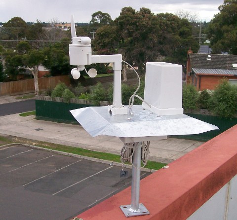
Многие погодные станции передают свои данные на частотепримерно 433 МГц, используя полосу, отведенную для маломощного нелицензионного использования.
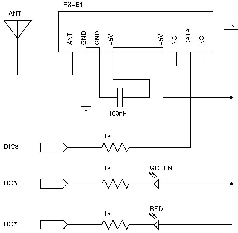
Метеостанция схема
Код Arduino
/**
* WeatherStationReceiver
*
* Receives and decodes a pulse-width and transition encoded RF
* bitstream, received through a 433MHz receiver module into the PB0
* Input Capture Pin (ICP).
*
* The transmitter is from the La Crosse WS-2355 Weather Station
* package, the RF transmitter is the integrated thermo/hygro station,
* (part number WS-2300-25S), and cable connections between the rain and
* wind sensors are made to the WS-2300-25S unit as it is the central RF
* transmitter. The cable connected rainfall sensor is part number
* WS-2300-16. The cable connected wind speed and direction sensor is
* part number TX20.
*
* Copyright 2009 Marc Alexander <marc.alexander@gmail.com>
* Copyright 2009 Jonathan Oxer <jon@oxer.com.au>
* http://www.practicalarduino.com/projects/weather-station-receiver
*/
/**
* NOTE:
* The rainfall count may be 11 bits, not 12 bits. Once I saw a 4000+
* reading on it that was not generated by rainfall pulses, so a higher
* bit there may mean something else? Still investigating.
*/
/**
* TODO:
* 1. Add: WSR_RESET() call from a dead-time timeout. If no RF
* activity is received within a few mS, reset the receiver state
* machine. Currently unsquelched RF noise is resetting it anyway
* given the receiver model used, but a quiet receiver timeout should be
* there also. Make sure boundary condition of reset just as new bit /
* period coming in is not a problem causing loss of packet start if
* reset happens during first transition/bit in.
*/
/*--------------------------------------------------------------------------------------
Includes
--------------------------------------------------------------------------------------*/
#include "WeatherStationReceiver.h"
/*--------------------------------------------------------------------------------------
Variables
--------------------------------------------------------------------------------------*/
//----------
// Timer 1 Input capture period and captured event time detection
uint uiICP_CapturedTime;
uint uiICP_PreviousCapturedTime;
uint uiICP_CapturedPeriod;
uint uiICP_PreviousCapturedPeriod;
byte bICP_CapturedPeriodWasHigh;
byte bICP_PreviousCapturedPeriodWasHigh;
unsigned long ulICP_Timestamp_262_144mS;
//----------
byte bICP_WSR_State; //Interpreter state machine
byte bICP_WSR_PacketData[WSR_PACKETARRAYSIZE][4+8]; //incoming RF packet data with 4 byte timestamp at start, already bit reversed to suit.
//main array size must be ^2, and there may be some other count dependencies in the interpreter.
byte bICP_WSR_PacketInputPointer; //
byte bICP_WSR_PacketOutputPointer; //
byte bICP_WSR_PacketInputBitPointer; //
uint uiICP_WSR_ReceivedPacketCount; //
//----------
// Saved timestamp at packet receive conversion
unsigned long ulWSR_LastTimestamp_262_144mS;
//----------
// Real world data, latest received and converted by Packet_Converter_WS2355()
byte bWSR_StationTransmitterID; //
sint siWSR_CurrentTemperature; //
byte bWSR_CurrentHumidity; //
byte bWSR_CurrentWindDirection; //
uint uiWSR_CurrentWindSpeed_m_per_sec; //
uint uiWSR_RainfallCount; //
unsigned long ulWSR_Rainfall_mm_x10;
//----------
const char strWindDirection[16][4] =
{
"N ", "NNE", "NE ", "ENE",
"E ", "ESE", "SE ", "SSE",
"S ", "SSW", "SW ", "WSW",
"W ", "WNW", "NW ", "NNW"
};
// Comment out for a normal build
// Uncomment for a debug build
//#define DEBUG
/**
* Initial configuration
*/
void setup(void)
{
Serial.begin( 38400 ); //using the serial port at 38400bps for debugging and logging
Serial.println( "Weather Station Receiver has powered up" );
Init_Ports();
Init_RF_Interpreters();
interrupts(); // Enable interrupts (NOTE: is this necessary? Should be enabled by default)
}
/**
* Main program loop
*/
void loop(void)
{
Packet_Converter_WS2355();
}
/**
* Initialise port initial state and data direction registers
*/
void Init_Ports()
{
DDRB = 0x2F; // B00101111
}
/*--------------------------------------------------------------------------------------
Packet_Converter_WS2355
Inspect, validate and convert any fresh incoming packet data to the latest real world values
bit 1 2 3 4 5 byte 1
<-TS 1234567890123456789012345678901234567890123456789012 00112233 4455667788990
/--||--\/--||--\/--||--\/--||--\/--||--\/--||--\/--|
1) 0000100101000010001001111000010100110011101011000001 00000043 0942278533AC1 st:34 ok: 23.3? (533 = 53.3deg, - 30.0deg offset)
ssiiiiiiii ttt
2) 0000100100010010001001111000010100001101101011111000 00000045 091227850DAF8 st:34 ok: 50% RH
ssiiiiiiii hh
3) 0000100100100010001001111000000010001100111101111000 00000046 092227808CF78 st:34 ok: 140 rainfall, 72.5 mm
ssiiiiiiii rrrrrrrrrrrr
4) 0000100101110010001001111000000000001100111111111101 00000047 097227800CFFD st:34 ok: W (12) wind, speed 0.0m/s 0.0km/h
ssiiiiiiii
5) 0000100101000010001001111000010100110011101011000001 00000049 0942278533AC1 st:34 ok: 23.3?
ssiiiiiiii
6) 0000100100010010001001111000010100001101101011111000 0000004A 091227850DAF8 st:34 ok: 50% RH
ssiiiiiiii
7) 0000100100100010001001111000000010001100111101111000 0000004B 092227808CF78 st:34 ok: 140 rainfall, 72.5 mm
ssiiiiiiii
8) 0000100101110010001001111000000000001100111111111101 0000004D 097227800CFFD st:34 ok: W (12) wind, speed 0.0m/s 0.0km/h
ssiiiiiiii wwww cccc
cccc = sum of all previous nibbles, from the start of the packet (all 48 preceding bits, 12 nibbles)
ss = sensor/packet identifier
wwww = wind direction
0 = N 1 = NNE 2 = NE 3 = ENE
4 = E 5 = ESE 6 = SE 7 = SSE
8 = S 9 = SSW 10 = SW 11 = WSW
12 = W 13 = WNW 14 = NW 15 = NNW
iiiiiiii = station ID byte. May not be using the top(left) bit of this byte, but is using bits 0-6 at least.
Every time the WS-2300-25S transmitter batteries are changed, it generates a new semi-random
station ID. The user is expected to power cycle the WS-2355 receiver which will then
'lock on' to the next received station ID.
rrrrrrrrrrrr = 12 (potential?) bits of rainfall count.
Note that it is up to the data analyser and any time window formatting
to treat this as a differential value only. It is expected that the value will
overflow in long term use.
For more data decoding and locations, see conversion code below
--------------------------------------------------------------------------------------*/
void Packet_Converter_WS2355(void)
{
byte b;
byte c;
sint si;
if( bICP_WSR_PacketInputPointer != bICP_WSR_PacketOutputPointer )
{
// A fresh packet is ready to check and convert
#ifdef DEBUG
if( (ulICP_Timestamp_262_144mS - ulWSR_LastTimestamp_262_144mS) > 8 )
{
// Blank separator line if there has been more than about 2 seconds since the last
// packet to make it easier to see what belongs with what
Serial.println();
}
#endif
#ifdef DEBUG
//print it in binary text out the serial port
Serial.print("BINARY=");
for( b = WSR_TIMESTAMP_BIT_OFFSET ; b < (WSR_RFPACKETBITSIZE+WSR_TIMESTAMP_BIT_OFFSET) ; b++ )
{
if( (bICP_WSR_PacketData[bICP_WSR_PacketOutputPointer][b >> 3] & (0x80 >> (b&0x07))) != 0 )
{
Serial.print( '1', BYTE );
} else {
Serial.print( '0', BYTE );
}
if( b == 31 )
Serial.print( ' ', BYTE ); //timestamp seperator
}
Serial.println();
//print it in hex text out the serial port
//Serial.print( ' ', BYTE );
Serial.print("HEX=");
for( b = 0 ; b < ((WSR_RFPACKETBITSIZE+WSR_TIMESTAMP_BIT_OFFSET)/4) ; b += 2 )
{
// One nibble at a time
c = bICP_WSR_PacketData[bICP_WSR_PacketOutputPointer][b >> 1];
// Top nibble
Serial.print( (c & 0xF0) >> 4, HEX );
// Bottom nibble, drop the last one since it's not part of the 52 incoming bits
if( b < (((WSR_RFPACKETBITSIZE+WSR_TIMESTAMP_BIT_OFFSET)/4)-1) )
Serial.print( (c & 0x0F), HEX );
// Timestamp seperator
if( b == 6 )
Serial.print( ' ', BYTE );
}
Serial.println();
#endif
//----------------------------------------------------------------------------
if( PacketAndChecksum_OK_WS2355 )
{
// Extract the station ID
b = (bICP_WSR_PacketData[bICP_WSR_PacketOutputPointer][5] << 4);
b += (bICP_WSR_PacketData[bICP_WSR_PacketOutputPointer][6] >> 4);
bWSR_StationTransmitterID = b;
// Print to serial port
Serial.print( "STATIONID=" );
Serial.println( bWSR_StationTransmitterID, DEC );
// Bits 4 and 5 of this byte are the sensor/packet ID
b = bICP_WSR_PacketData[bICP_WSR_PacketOutputPointer][5];
b = (b >> 4) & 0x03;
switch( b )
{
case 0:
{
// 0: temperature
// Sensor/packet ID bits are 0x00, temperature is present in this packet
// Lower nibble of byte 7 is first temperature digit, take care of 3xx offset
si = ((bICP_WSR_PacketData[bICP_WSR_PacketOutputPointer][7] & 0x0F) * 100);
si += ((bICP_WSR_PacketData[bICP_WSR_PacketOutputPointer][8] >> 4) * 10);
si += (bICP_WSR_PacketData[bICP_WSR_PacketOutputPointer][8] & 0x0F);
siWSR_CurrentTemperature = (si - 300);
// Print to serial port with decimal place management
Serial.print("TEMPERATURE=");
Serial.print( (siWSR_CurrentTemperature/10), DEC );
Serial.print( '.', BYTE );
if( siWSR_CurrentTemperature < 0 ) {
Serial.println( ((0-siWSR_CurrentTemperature)%10), DEC );
} else {
Serial.println( (siWSR_CurrentTemperature%10), DEC );
}
break;
}
case 1:
{
// 1: humidity
//sensor/packet ID bits are 0x01, humidity is present in this packet
c = ((bICP_WSR_PacketData[bICP_WSR_PacketOutputPointer][7] & 0x0F) * 10);
c += (bICP_WSR_PacketData[bICP_WSR_PacketOutputPointer][8] >> 4);
bWSR_CurrentHumidity = c;
// Print to serial port with decimal place management
Serial.print("HUMIDITY=");
Serial.println( bWSR_CurrentHumidity, DEC );
break;
}
case 2:
{
// 2: rainfall
si = (sint)(bICP_WSR_PacketData[bICP_WSR_PacketOutputPointer][7] & 0x0F) << 8;
si += bICP_WSR_PacketData[bICP_WSR_PacketOutputPointer][8];
uiWSR_RainfallCount = (uint)si;
// Killer (for the Arduino) long multiply here, put in for now to demo real mm of rainfall maths
ulWSR_Rainfall_mm_x10 = (((unsigned long)uiWSR_RainfallCount * 518) / 100);
// Print to serial port
Serial.print("RAINFALL=");
Serial.print( (ulWSR_Rainfall_mm_x10/10), DEC );
Serial.print( '.', BYTE );
Serial.println( (ulWSR_Rainfall_mm_x10%10), DEC );
break;
}
case 3:
{
// 3: wind direction and speed
// Sensor/packet ID bits are 0x03, wind data is present in this packet
// Wind direction
bWSR_CurrentWindDirection = (bICP_WSR_PacketData[bICP_WSR_PacketOutputPointer][8] & 0x0F);
//wind speed, decimal value is metres per second * 10 (1 fixed deciml place)
si = (sint)(bICP_WSR_PacketData[bICP_WSR_PacketOutputPointer][7] & 0x10) << 4;
si += ((bICP_WSR_PacketData[bICP_WSR_PacketOutputPointer][7] & 0x0F) << 4);
si += (bICP_WSR_PacketData[bICP_WSR_PacketOutputPointer][8] >> 4);
uiWSR_CurrentWindSpeed_m_per_sec = (uint)si;
// Print to serial port with decimal place management
Serial.print("WINDDIRECTION=");
Serial.println( strWindDirection[bWSR_CurrentWindDirection] );
Serial.print("WINDSPEED=");
Serial.print( (uiWSR_CurrentWindSpeed_m_per_sec/10), DEC );
Serial.print( '.', BYTE );
Serial.println( (uiWSR_CurrentWindSpeed_m_per_sec%10), DEC );
break;
}
default:
{
break;
}
}
} else {
Serial.print( " bad checksum or packet header" );
}
//----------------------------------------------------------------------------
//save the last timestamp value, currently used for extra CR/LF in serial print
ulWSR_LastTimestamp_262_144mS = ulICP_Timestamp_262_144mS;
//----------------------------------------------------------------------------
//conversion process done on this packet, move the output pointer along
bICP_WSR_PacketOutputPointer = ((bICP_WSR_PacketOutputPointer+1)&(WSR_PACKETARRAYSIZE-1));
}
}
/**
* PacketAndChecksum_OK_WS2355
* Return true if packet checksum and inspection is ok
*/
byte PacketAndChecksum_OK_WS2355(void)
{
byte dataPos;
byte checksum;
// First check, last 4 bits of packet are sum of the previous 48 bits (12 nibbles)
// Don't forget to offset past the timestamp in the first 4 bytes
checksum = 0;
for( dataPos = 4; dataPos < 10; dataPos++ )
{
// Checked a byte at a time, accumulate into checksum
checksum += (bICP_WSR_PacketData[bICP_WSR_PacketOutputPointer][dataPos] >> 4);
checksum += (bICP_WSR_PacketData[bICP_WSR_PacketOutputPointer][dataPos] & 0x0F);
}
checksum &= 0x0F;
if( checksum != (bICP_WSR_PacketData[bICP_WSR_PacketOutputPointer][10] >> 4) )
{
return( false ); // Checksum does not match
}
// Second check, first byte of packet must be 0x09 ( B00001001 ), appears to be
// the main identifier for this station
if( bICP_WSR_PacketData[bICP_WSR_PacketOutputPointer][4] != 0x09 )
{
return( false );
}
return( true );
}
/**
* Init_RF_Interpreters
*/
void Init_RF_Interpreters(void)
{
//Call macros that reset any RF_Interpreter_... state machine and housekeeping values
WSR_RESET();
//RF decode ports setup
//Marc making PB0 (ICP1 Input Capture) a floating input for RX ASK bitstream receiving
//PB0 was used by the Color LCD/Joystick Shield for the backlight_on signal,
//R2 has now been removed on the lcd pcb, and Q1 C-E shorted to keep the BL always on
DDRB &= ~(1<<DDB0); //PBO(ICP1) input
PORTB &= ~(1<<PORTB0); //ensure pullup resistor is also disabled
//PORTD6 and PORTD7, GREEN and RED test LED setup
DDRD |= B11000000; //(1<<PORTD6); //DDRD |= (1<<PORTD7); (example of B prefix)
GREEN_TESTLED_OFF(); //GREEN test led off
RED_TESTLED_ON(); //RED test led on
//PORTD |= _BV(PORTD6); //GREEN test led off (example of _BV macro)
//PORTD &= ~_BV(PORTD7); //RED test led on (example of _BV macro)
//PORTD |= (1<<PORTD6); //GREEN test led off (example of AVR studio style)
//PORTD &= ~(1<<PORTD7); //RED test led on (example of AVR studio style)
//---------------------------------------------------------------------------------------------
//ICNC1: Input Capture Noise Canceler On, 4 successive equal ICP1 samples required for trigger (4*4uS = 16uS delayed)
//ICES1: Input Capture Edge Select 1 = rising edge to begin with, input capture will change as required
//CS12,CS11,CS10 TCNT1 Prescaler set to 0,1,1 see table and notes above
TCCR1A = B00000000; //Normal mode of operation, TOP = 0xFFFF, TOV1 Flag Set on MAX
//This is supposed to come out of reset as 0x00, but something changed it, I had to zero it again here to make the TOP truly 0xFFFF
TCCR1B = ( _BV(ICNC1) | _BV(CS11) | _BV(CS10) );
SET_INPUT_CAPTURE_RISING_EDGE();
//Timer1 Input Capture Interrupt Enable, Overflow Interrupt Enable
TIMSK1 = ( _BV(ICIE1) | _BV(TOIE1) );
}
/*--------------------------------------------------------------------------------------
TIMER1_OVF_vect
Timer1 overflow interrupt routine
262.144 mS TOF period
If used to feed a 32 bit timestamp counter, (0xFFFFFFFF = 4294967295 count before overlow)
= 1125899906 seconds = 18764998 minutes = 312749 = 13031 days = 35 years.
--------------------------------------------------------------------------------------*/
ISR( TIMER1_OVF_vect )
{
//increment the 32 bit timestamp counter (see overflow notes above)
//overflow is allowed as this timestamp is most likely to be used as a delta from the previous timestamp,
//so if it's used externally in the same 32 bit unsigned type it will come out ok.
ulICP_Timestamp_262_144mS++;
}
/*--------------------------------------------------------------------------------------
TIMER1_CAPT_vect
Timer1 input capture interrupt routine
--------------------------------------------------------------------------------------*/
ISR( TIMER1_CAPT_vect )
{
// Immediately grab the current capture time in case it triggers again and
// overwrites ICR1 with an unexpected new value
uiICP_CapturedTime = ICR1;
// GREEN test led on (flicker for debug)
GREEN_TESTLED_ON();
//----------------------------------------------------------------------------
//immediately grab the current capture polarity and reverse it to catch all the subsequent high and low periods coming in
//If the initial period filter passes below, this will be inspected to become bICP_EventPolarity
if( INPUT_CAPTURE_IS_RISING_EDGE() )
{
SET_INPUT_CAPTURE_FALLING_EDGE(); //previous period was low and just transitioned high
bICP_CapturedPeriodWasHigh = false; //uiICP_CapturedPeriod about to be stored will be a low period
} else {
SET_INPUT_CAPTURE_RISING_EDGE(); //previous period was high and transitioned low
bICP_CapturedPeriodWasHigh = true; //uiICP_CapturedPeriod about to be stored will be a high period
}
//----------------------------------------------------------------------------
//calculate the current period just measured, to accompany the polarity now stored
uiICP_CapturedPeriod = (uiICP_CapturedTime - uiICP_PreviousCapturedTime);
//----------------------------------------------------------------------------
// RF Pulse filtering, width test and polarity are analysed now, call the
// interpreter(s) to analyse them
RF_Interpreter_WS2355( /*uiICP_CapturedPeriod, bICP_CapturedPeriodWasHigh*/); //arguments removed and made global
//----------------------------------------------------------------------------
//save the current capture data as previous so it can be used for period calculation again next time around
uiICP_PreviousCapturedTime = uiICP_CapturedTime;
uiICP_PreviousCapturedPeriod = uiICP_CapturedPeriod;
bICP_PreviousCapturedPeriodWasHigh = bICP_CapturedPeriodWasHigh;
//GREEN test led off (flicker for debug)
GREEN_TESTLED_OFF();
}
/*--------------------------------------------------------------------------------------
RF_Interpreter_WS2355
The WS2355 sends 52 bits in a packet and the format is
A long high followed by a long low is 0
A short high followed by a long low is 1
Not much more is done in this input capture interrupt routine apart from the
00001 leader check and then loading of the full 52 bit packet.
bICP_WSR_PacketInputPointer will be moved along when received, the main loop
called Packet_Converter_WS2355() routine will do the rest of the work
to check and convert each packet's data content.
--------------------------------------------------------------------------------------*/
void RF_Interpreter_WS2355( /*uiICP_CapturedPeriod, bICP_CapturedPeriodWasHigh*/ )
{
volatile byte b;
byte bValidBit = false; // 0=false(WSR_BIT_NONE), 1=WSR_BIT_ZERO, 2=WSR_BIT_ONE
//#warning A quiet-time timeout must be added to this interepreter, to reset the state machine any time there is a long quiet break in rx
//discard the captured period if it is out of the expected range, it is noise...
if( (uiICP_CapturedPeriod >= WSR_PERIOD_FILTER_MIN) && (uiICP_CapturedPeriod <= WSR_PERIOD_FILTER_MAX) )
{
//----------------------------------------------------------------------------
//PERIOD INITIAL DURATION FILTER OK, CONTINUE
//----------------------------------------------------------------------------
//Check if this is a valid zero(long high) or one(short high) bit, or low period in between
if( bICP_CapturedPeriodWasHigh )
{
//got a high period, could be a valid bit
if( (uiICP_CapturedPeriod >= WSR_SHORT_PERIOD_MIN) && (uiICP_CapturedPeriod <= WSR_SHORT_PERIOD_MAX) )
{
//short high, valid one bit
bValidBit = WSR_BIT_ONE;
} else if( (uiICP_CapturedPeriod >= WSR_LONG_PERIOD_MIN) && (uiICP_CapturedPeriod <= WSR_LONG_PERIOD_MAX) ) {
//long high, valid zero bit
bValidBit = WSR_BIT_ZERO;
} else {
//invalid high period, in the dead zone between short and long bit period lengths
WSR_RESET();
}
}
//else
//{
// //got a low period, ignored
//}
//----------------------------------------------------------------------------
//Enter the state machine to load and prepare the incoming packet to bICP_WSR_PacketData[8][4+8]
if( bValidBit != false )
{
switch( bICP_WSR_State )
{
case WSR_STATE_IDLE:
{
if( bValidBit == WSR_BIT_ZERO )
{
//first bit of valid packet is zero (4 zero's, maybe 3)
//zero out the appropriate bit on the current input packet
bICP_WSR_PacketData[bICP_WSR_PacketInputPointer][bICP_WSR_PacketInputBitPointer >> 3]
&= ~(0x01 << (bICP_WSR_PacketInputBitPointer&0x07));
bICP_WSR_PacketInputBitPointer++;
bICP_WSR_State = WSR_STATE_LOADING_BITSTREAM;
} else {
WSR_RESET();
}
break;
}
case WSR_STATE_LOADING_BITSTREAM:
{
// Potentially valid packet bitstream is on its way in, keep loading it up
if( bValidBit == WSR_BIT_ZERO )
{
bICP_WSR_PacketData[bICP_WSR_PacketInputPointer][bICP_WSR_PacketInputBitPointer >> 3]
&= ~(0x80 >> (bICP_WSR_PacketInputBitPointer&0x07));
} else {
bICP_WSR_PacketData[bICP_WSR_PacketInputPointer][bICP_WSR_PacketInputBitPointer >> 3]
|= (0x80 >> (bICP_WSR_PacketInputBitPointer&0x07));
}
// Check at appropriate location of the incoming bitstream, if it is valid and throw away if not
if( bICP_WSR_PacketInputBitPointer == (WSR_TIMESTAMP_BIT_OFFSET + 4) )
{
// 01234 01234
// Acceptable start to packet is 00001 or 00010 (lost the first 0), could optimise
// this but will leave with b for now for stability and debugging
b = bICP_WSR_PacketData[bICP_WSR_PacketInputPointer][4/*bICP_WSR_PacketInputBitPointer >> 3*/];
b &= B11111000;
if( b == B00010000 )
{
//valid packet 00010 start (with lost first zero), realign and continue
bICP_WSR_PacketData[bICP_WSR_PacketInputPointer][4/*bICP_WSR_PacketInputBitPointer >> 3*/] = B00001000;
bICP_WSR_PacketInputBitPointer++; //move up one past the inserted missing bit
} else if( b != B00001000 ) {
//invalid packet start, not 00001, reset
WSR_RESET();
}
}
// Final check, has the last packet bit (52 bits total) come in? If so, mark this packet
// as done and move the major packet input pointer along
if( bICP_WSR_PacketInputBitPointer == (WSR_TIMESTAMP_BIT_OFFSET + (WSR_RFPACKETBITSIZE-1)) )
{
// Got full packet, timestamp it for the main loop
bICP_WSR_PacketData[bICP_WSR_PacketInputPointer][0] = byte(ulICP_Timestamp_262_144mS >> 24);
bICP_WSR_PacketData[bICP_WSR_PacketInputPointer][1] = byte(ulICP_Timestamp_262_144mS >> 16);
bICP_WSR_PacketData[bICP_WSR_PacketInputPointer][2] = byte(ulICP_Timestamp_262_144mS >> 8);
bICP_WSR_PacketData[bICP_WSR_PacketInputPointer][3] = byte(ulICP_Timestamp_262_144mS);
// Pointer and packet count
bICP_WSR_PacketInputPointer = ((bICP_WSR_PacketInputPointer+1)&(WSR_PACKETARRAYSIZE-1));//only the lower three bits are used for the 8 entry array
uiICP_WSR_ReceivedPacketCount++; //note will overflow and wrap, used for display of progress only
WSR_RESET();
}
// Increment pointer to next new bit location
bICP_WSR_PacketInputBitPointer++;
break;
}
}
}
//----------------------------------------------------------------------------
} else {
//----------------------------------------------------------------------------
// PERIOD OUT OF BOUNDS, DISCARD
// This will throw away any out of range periods and reset the state machine, high or low.
//----------------------------------------------------------------------------
WSR_RESET();
}
}
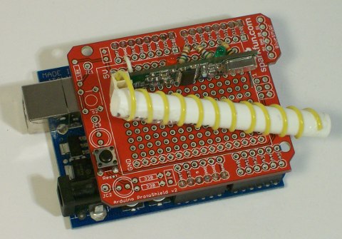
Готовое изделие